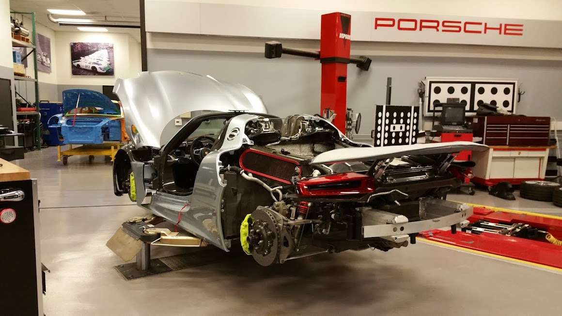
918 Porsche Spyder

918 Porsche Spyder

Saturday, July 11, 2015

Part 1 - Vehicle communication networks

Did you know that a modern day European vehicle typically has over 20 electronic computers.  These control modules are designed to process immense amounts of data.  This data ranges from time sensitive critical engine control inputs and outputs, transmission control, body electrical comfort features and critical safety systems to name a few.

An example of how CAN bus works; you step on your accelerator pedal, you expect your vehicle to move relative to your input on the gas pedal.  This physical movement is sensed by a duo of sensors that utilize hall effect sensors to output a set of linear voltages.  These pieces of data are hard wired to the engine control module.  The control module will process this analog data and will convert it to a digital signal for internal processing and sharing.


What do I mean by sharing?  There are other control systems that needs the information about your intent to accelerate.  Why?  The transmission needs to know this so it can properly shift gears, the stability system/ABS needs this info and of course many other system control modules for various control reasons that will be covered at a later time.  The data created by your movement on the accelerator pedal is now outputted on the CAN network as a coded message for any other control modules on the network to utilize for there respective analysis to create an effect or action to do work.

The data created by the gas pedal is a coded message when on the CAN network, lets say that the only module that needed this information was the transmission control module.  It now will begin to downshift the transmission via its internal hydraulic system.  Before your vehicle will accelerate though, your engine needs to breathe more. What I mean by this is that your air intake which is adjusted via the Throttle body must open its throttle blade to allow more air into the engine.  This in turn will affect other sensors that will feedback hardwired data back to the engine control module.  The engine control module will modify your fuel injection on time, ignition system and camshaft timing at a minimum.  This will allow for your acceleration to occur.

All of this data transmission needs to occur fast and reliably so that the driver does not experience erroneous non designed hesitations or worse yet failures.

What I have described up to now is a very simplified example of how CAN works.  It is more involved but lets start with a bit of reviewing.

What automotive engineers have been utilizing since the early 80's is what is called multiplexing.  Multiplexing allows for the vehicle input-output of sensor values, actuator control and transmittal  of data over a set of wires in parallel between the networks control modules.  This allows for communication without having to utilize immense amounts of wiring.  One of the benefits for CAN is less wires/looms in vehicle equates to less vehicle weight.  This improves fuel economy.  CAN allows for more advanced Electro-mechanical systems to be installed and used on present day vehicles.  Current safety systems require near instant information the vehicles dynamics and condition via a multitude of sensors.


The modules communicate with each other by sending coded serial data messages over the network. The data
messages are available to all of the control modules connected to the network. Modules connected to a multiplex circuit are often called nodes.


CAN bus networks allow for communication speeds of up to 500 K bits per second.  The data that is transmitted occurs over 2 twisted wires.  The majority of your vehicles sensors on a vehicle output analog data, voltages, resistances, amperage.  The voltages can be at certain frequencies and amplitudes, the resistances can vary from low ohm-age to mega-ohms, the amperes can be near to zero to milliamps.  All of this data is converted to binary codes internally in a control module.  In fact it is converted so the control module can understand the analog data for its own analytical purposes. Lets say your input on the gas pedal earlier was equivalent to a voltage value of 3.5 volts and 2.5 volts.  In binary code this would look like the following; 00110011 00101110 00110101 00100000 01110110 01101111 01101100 01110100 01110011 00100000 00110010 00101110 00110101 00100000 01110110 01101111 01101100 01110100 01110011.  Lots of zeros and ones!  This is how automotive computers communicate with each other.


CAN was created by Bosch in 1983, 1992 Mercedes Benz had the first vehicles with CAN bus networks, in 2008 all vehicles were mandated to have CAN bus installed in vehicles.  CAN is the following in a nutshell:


  • A way for multiple vehicle computers-modules to communicate with each other
  • CAN supports and allows bi-directional communication between modules
  • CAN communication speeds can reach up to 500 kilo bits per second and can handle large amounts of data
  • Utilizes a twisted differential pair of wires for communication paths
  • Computers-modules on network are called Nodes
  • All Nodes see all messages on the respective Bus - this means it is a Peer to Peer network
  • Each message- piece of data has a unique Identifier code
  • The most important piece of data with the highest priority will always gain access to the bus ahead of lower priority messages

To be Continued........


Monday, August 4, 2014

Porsche Hall Effect Cam Sensors

Bosch Camshaft Sensor Bank 1 & 2 Intake

 Hall sensors are used to determine camshaft position and provide the DME with information regarding camshaft adjustment positions as well.  The signals are needed to allow the DME to time the injection and ignition as well.  The technical aspects of this sensor are based on the Hall Effect signal generation method.  This method allows for exact calculations of the positions of the intake camshafts; the camshafts have a pressed rotor on the end of end of the intake camshaft facing the front of the engine.  Bank 2 camshaft rotor is also on the rear end of the intake camshaft as well, but faces the flywheel side. 

The hall sensor contains a permanent magnet, 2 hall elements and a current bearing semi-conductor plate.  The rotating of the tone wheel rotor will cause an interruption of the magnetic field generated by the hall sensor, when this happens at right angles a voltage is induced in the hall sensor.  This voltage signal is an on and off digital signal that is representative of the exact camshaft position and allows for Vario-cam adjustment and diagnosis.

The DME 5.2.2. uses a simple camshaft rotor with only one notched tooth.  There is also a rotor on each bank but in different positions.  Bank 1 has the rotor pressed on the intake camshaft on the flywheel end of the camshaft.  Bank 2 has the rotor at the front of the engine.  The signals are also used to determine cylinder position and for camshaft adjustment diagnosis.

Dme 7.2, 7.8, 7.8_40 camshaft hall position sensors accurately detect the positions of the camshaft 8 times per shaft revolution, that works out to 4 times per crankshaft rotation.  The DME is able to use the camshaft signals to enable a quick start feature.  The DME will know the exact camshaft position on engine shutdown, this is stored in the Dme’s RAM and used on the next startup, this allows the engine controller to start injection and ignition immediately without having to wait for 16 signals.  This allows for an engine start in less than 1 crankshaft revolution and also can let the car start without a engine speed sensor signal.  Note that the Dme 5.2.2 does not have this feature and will not start if the engine speed sensor signal is not received by the DME.

For the Dme to exactly determine the timing of the engine, it needs to see bank 1 hall sensor and the engine speed sensor reference mark in a particular position. When this happens the DME will be able to determine cylinder 1 and 4 positions and then will time and release the ignition and the sequential injection.  This sensor is also used in conjunction with the knock sensors to determine which cylinder is knocking.  The hall sensors are also used for camshaft position adaptation, this adaptation is needed so that the DME can react to deviations in timing caused by normal wear on the timing components.  If the battery is disconnected this adaptation is lost, so the DME must readapt the camshaft adaptations via normal driving.
Problem symptoms

  • Faulted hall sensors can cause hard starts.
  • Engine misfire codes with no actual misfire
  • Actual engine misfire events present
  • Vario cam adjustment fault codes due to erroneous signals
  • No or incorrect Vario-cam adjustment due to erroneous signals


Diagnostic Techniques

A Fault code for a bad hall sensor is not common, so when you want to make sure that your sensor is operating properly you can use a DSO to analyze the signals for proper signal generation, compared bank to bank.  You should get a total of 4 on off signals, reference the diagram for different DME version signals.  The use of a DSO will also allow you to determine if cam timing deviation exists, this is usually caused by a Vario cam system failure that will be discussed in the timing section.

                                  Example of good 2009 997 Bank 1-2 Cam sensor timing patterns


                      9PA known good bank to bank intake timing

                     
                         987 Known good Intake cam to cam timing

Tuesday, February 2, 2010

Advanced Diagnostic's


Circuit-System Testing

There will be 3 basic types of electrical wiring/component faults.
For engine performance faults, you will always have X amount of probable causes. It will be to your advantage to not always use the old age adage that it's usually this that is the problem. It is true that certain vehicles will eventually produce pattern failures, known parts or systems that go bad.

Types of Electrical Problems
• High Resistance Faults
• Low Resistance Faults
• Component Faults
• Intermittent circuit/component failures

Circuit Failure Testing ( Consumer/Function operates intermittently).

If you have a failure that is not always present, intermittent failures can and will be the most difficult to diagnose. If the system is electronically controlled, and its control module is capable of storing a fault code, try to retrieve the fault code with a scan tool. Fault codes will always be a guide to diagnosis and will give you the most probable causes of the fault. There usually is a flow chart tree that will guide you in your diagnosis. There will be times when it is also useful for you to deviate from the test plan and create your own test plan. Think outside of the box.
Remember to that it is vital to gather the following information about any intermittent problem.
• When does the function fail?
• Are any other functions affected?
• Were any other functions in operation at the time of failure?
• Is the failure related to a vibration or bump occurrence?
• Does the failure occur at any specific temperature, time of the day, engine or transmission operating condition?
• Try to recreate the failure by operating the vehicle under the conditions observed at time of problem or described by client.
• If the failure can be replicated, proceed to with general diagnostic tests for the symptoms you observe or feel.
• Warning
• When performing a wire or circuit "wiggle test" make sure that the circuit being tested is not related to the airbag circuits.


Basic Electrical Faults

Basic electrical circuit faults can be categorized as follows:

Open Circuit

An open circuit is a break in the path of current flow. A circuit’s path must be complete from start to end, only then will current flow. An open circuit can be caused by a bad electrical connector or electrical pins with bad crimps, cracked wiring at the crimps, and broken wire strands and faulted components as well. It is essential to understand that if the circuit is powered, it will have voltage potential that will be present in the portion of the circuit that is still connected to the power source. It's also important to know that a bad ground of a circuit or component or connection will increase resistance.

With parallel circuits, an open circuit in one branch of the circuit will stop operation in that branch, but the other branches will continue to operate. An Ohmmeter test can determine if a circuit is open (infinite resistance). Remember that when you are testing for resistance in a circuit to test the integrity of the wiring, you must disconnect the power source and the other end of wire that goes to the component. It all depends on the circuit. As I describe the engine management’s sensor and actuators later in the book, you will see how the wiring tests can be performed.

A voltmeter from a Dvom can also be used to determine an open circuit by measuring the available voltage at various points of the circuit or the voltage drop between two points in the circuit. This procedure also helps to find and determine the location of the open circuit.

High Resistance

A high resistance circuit is a circuit with more resistance than specified. Any circuit resistance should typically in the components that perform work. High resistance will reduce the amount power, current and voltage that should be available to the components connected to the circuit.

High resistance in a circuit can be caused by loose, dirty or corroded connections or internal component failures. Broken strands of wire within the insulation will also increase the circuit’s resistance. When diagnosing a circuit for high resistance, try not to disturb the connections until you have narrowed down the possible area of high resistance. The reason behind this is that you may unintentially clean off corrosion in a connector. This might temporarily correct the fault and make your diagnosis more difficult to isolate.

You can use an ohmmeter to test an unpowered circuit; this will allow you to determine if you have high resistance in the circuit. But the preferred way to test for resistance is using the voltage drop method. We will get into this test method in just a bit.

Low resistance

A short circuit is a low resistance fault that allows too much current to flow to ground due to the low resistance. This will typically blow a fuse or damage wiring or components. Remember that low resistance is always caused by a short to ground or an unwanted ground.

Short circuit to ground

A short circuit to ground occurs when the circuit is grounded or partially grounded where it’s not designed to. Typically with Porsche this is usually caused by radio or accessory installations or body shop wiring repairs or the lack of. If there is a short circuit to ground after the load, the circuit control may be lost, causing operation of components when it is not wanted.

To diagnose a short circuit to ground in a fused circuit, systematically disconnecting circuit components until your voltmeter reads 0 V will identify the area of the short circuit.

Short circuit to power

A short circuit to voltage happens when the insulation fails causing the wire strands to contact the voltage of another circuit. This will cause the circuit or circuits to operate incorrectly. You should carefully observe the symptoms and refer to the appropriate wire diagram to understand the circuit operation flow. Remove fuses until the circuit is isolated, and then measure resistance and voltage to find the problem area.

Component faults

Sensors or Actuators or control units can fail and be faulty even when the part is new. This is definitely the most difficult part of diagnosis, since most of us don’t just have spare parts lying around to plug in and see what happens. But once you have verified that the wiring is ok and that the proper control signals and voltages and grounds to a component are present, then you can start to isolate the failure to a component. I will indicate the proper signals and resistance values and scope patterns that show what a bad and good component look like.

Components can fail from normal wear and tear or an outright defect with the part.

Saturday, September 5, 2009


This is the first part of the Engine Management Basics. I hope that it is interesting and useful information for all of you.

The goal of the fuel system is to maintain the air fuel ratio at the most efficient air to fuel ratio, this is called Stoichiometric. This means that the Air to fuel ratio is 14.7 parts of air to 1 part of fuel. This ratio is called Lambda in German, and is displayed on a Factory style scan tool as either Actual Lambda, Oxygen sensing or Fuel trim mean value. This Lambda value is displayed as 1 and is the equivalent to the Stoichiometric ratio.

Lambda= Air mass (Mass Air Flow) divided by the theoritical required air mass

Lambda less than 1= a lack of air or rich mixture

Lambda greater than 1= an excess of air or lean mixture

When these values are displayed on a scan tool, they indicate the actual air fuel mixture and the health of the engine as well.
It is important to know that if you are using a generic OBD II scanner the Lambda value will not be displayed, but will be shown as short term and long term fuel trim. This will be discussed in detail in later posts though.

Porsche uses a Closed loop Feedback fuel management system that has a goal. The DME's ultimate duty is to make sure that emissions do not exceed a certain limit. To do this it needs a variety of sensors and other components that will work in harmony to not only keep emissions under control, but also produce good driveabilty and power at the same time. The engine management system contains map programs that are base starting points and are able to be modified to produce the most optimal performance.

The closed loop feedback systems main input sensors are the Mass air flow sensor and the oxygen sensors before the catalytic converters. The use of the oxygen sensors are essentially information sensors that enable the DME to determine if the fuel mixture control is actually doing its job correctly. Think of these sensors like an EKG of the engines overall health. The outputted signals that they produce are extremely useful for engine performance diagnostics. Diagnosis by analyzing the oxygen sensors will be discussed in the future. For now lets go over how the DME engine control unit determines the amount of fuel that will be needed to in proportion to your accelertor pedal request.

*The DME will look at the mass air flow and the engine speed.
*Then the controller will access its programmed injector duration map.
*Dme determines the injector pulse width on-off time for your given engine load and speed range.
*Dme will analyze the oxygen sensor signal inputs and determine the exact fuel mixture that is needed.
*Injector pulse width is modified and fine tuned based on the oxygen sensor input

The oxygen sensor is really the heart of the fuel mixture system, without it the DME would not be able to control emissions.
This sensor's signal must stay within a certain range and average, when this is accomplished the catalytic converter will be able to function at its most optimal potential by reducing the gases HC, CO and NOx. The oxygen sensor operates on the galvanic concentration cell principle. Think of this sensor as a battery that can generate voltage. It consists of a ceramic Nernst cell that is made up of ceramic sheets of wafers coated with platinum and are porous as well. When the sensor is at operating temperature of 650*F. thanks to an internal heater, it will react to the exhaust gases concentration of oxygen or lack of it. The sensor has a reference channel to the outside atmosphere which is used for differential measurement. It is important to note that the wiring harness for these sensors should never be repaired as it can affect the flow of air to the reference channel at the top of the sensor.

When there is a difference in oxygen content between the reference air channeled into the sensor and the exhaust stream on the outside of the sensor, then the oxygen ions will migrate from the inside of the sensor to the outside electrodes in the sensor. This creates a voltage in the range of 0.1 millivolts and 0.9 millivolts. This voltage input to the DME is proportional to the air fuel ratio. If the sensor's average is in the range of 450 mv then this is indicative of Lambda 1 and allows for effective control of emissions. Its important to remember that if the internal heater fails or is failing intermittently, it can effect engine performance and fuel economy. The reason why is that the sensor must stay above 650*F. to be able to generate voltage, if the sensor is not at the right temperature, you can get partial voltage switching that can cause excess lean or rich conditions.

More to come in due time.